
How to Work an Air Compressor: The Direct Answer
To work an air compressor, connect it to a power source, attach the appropriate hose and tool fitting, set the regulator to the correct output pressure for your application, switch the unit on, and wait for the tank to pressurize before use. Never exceed the maximum rated PSI printed on the tank. That is the core process — but doing it safely, efficiently, and correctly over the long term requires understanding your specific compressor type, its controls, and its maintenance demands.
Air compressors range from small 1-gallon portable units to large industrial air compressors delivering thousands of cubic feet per minute. The two dominant types in industrial and professional settings are the piston air compressor (reciprocating) and the screw air compressor (rotary). Each works differently and is operated differently. This guide covers both in full detail alongside universal operating principles.
Key Components of an Air Compressor You Must Know Before Operating
Before touching any controls, identify and understand the function of each major component. Misidentifying a control — such as confusing the regulator with the unloader valve — can lead to dangerous pressure errors or equipment damage.
- Motor / Engine: Drives the pump. Electric motors are rated in horsepower (HP); portable gas-powered units use small engines. Industrial air compressors typically range from 5 HP to 500+ HP.
- Pump / Compression Element: The mechanism that compresses air — a piston-cylinder assembly in reciprocating compressors, or a pair of meshing helical rotors in screw compressors.
- Receiver Tank: Stores compressed air and smooths pressure delivery. Capacity is measured in gallons or liters — from 1 gallon (portable) to 500+ gallons (industrial). Tanks have a maximum working pressure (MAWP) stamped on the shell.
- Pressure Gauge (Tank Gauge): Displays the actual pressure inside the storage tank in PSI or bar. This tells you how much reserve air is stored.
- Regulator: A manually adjustable valve that controls the output pressure delivered to your tool — independently of the higher pressure inside the tank. Pull up and turn to adjust; push down to lock the setting.
- Output (Regulated) Pressure Gauge: Displays the downstream pressure after the regulator — this is the pressure your tool actually receives.
- Safety Relief Valve: Automatically releases air if pressure exceeds the tank's safe limit. Never tamper with or block this valve — it is your last line of defense against catastrophic tank failure.
- Drain Valve: Located at the bottom of the tank. Used to drain condensed water that accumulates inside the tank during operation.
- Pressure Switch: Automatically starts and stops the motor when tank pressure drops below the cut-in point or rises to the cut-out point. For example, a compressor set to 90–120 PSI starts at 90 and stops at 120 automatically.
- Air Filter / Intake Filter: Prevents dust and debris from entering the pump. A clogged intake filter reduces flow and increases pump wear.
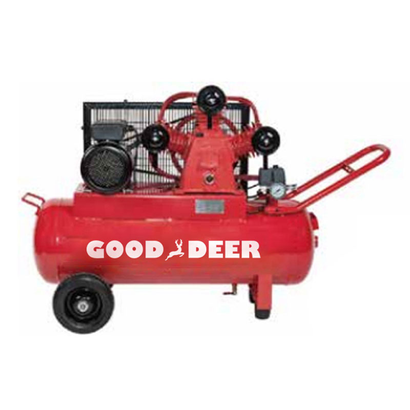
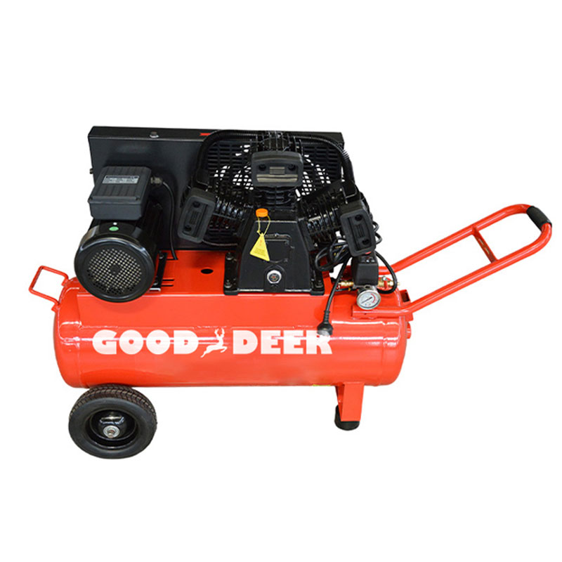
How a Piston Air Compressor Works
A piston air compressor (also called a reciprocating air compressor) uses one or more pistons driven by a crankshaft to compress air inside a cylinder — the same fundamental principle as a car engine, but in reverse. It is the most widely used compressor type for workshops, automotive shops, construction sites, and light-to-medium industrial applications.
Single-Stage vs. Two-Stage Piston Compressors
In a single-stage piston compressor, air is drawn in and compressed in one stroke to the final pressure — typically up to 150 PSI. These units suit most shop tools, inflation, and spray painting. In a two-stage piston compressor, air is compressed first by a large-diameter cylinder to an intermediate pressure (~90 PSI), cooled through an intercooler, then compressed again by a smaller cylinder to the final pressure — typically 175–200 PSI. Two-stage compressors run cooler, last longer under continuous use, and are the standard for heavy-duty industrial applications.
Oil-Lubricated vs. Oil-Free Piston Compressors
- Oil-lubricated: Uses oil to lubricate the piston rings and cylinder walls. Quieter, longer-lived (typically 15,000–20,000 hours), and suited for high-duty-cycle work. Requires oil level checks and oil changes every 500–1,000 hours.
- Oil-free: Uses permanently lubricated Teflon-coated rings. Lighter and maintenance-free but runs hotter, is noisier, and typically lasts 2,000–5,000 hours. Suitable for medical, food, and sensitive environments where oil contamination is unacceptable.
Duty Cycle — The Critical Piston Compressor Limitation
Piston compressors have a rated duty cycle — the percentage of time they can run continuously without overheating. A compressor with a 50% duty cycle can run for 30 minutes out of every hour. Exceeding the duty cycle causes overheating and premature valve and ring failure. Industrial-grade two-stage piston compressors often have 75–100% duty cycles. Consumer-grade single-stage models are frequently 50% or less — a critical consideration for sustained production use.
How a Screw Air Compressor Works
A rotary screw air compressor uses two intermeshing helical rotors — a male rotor and a female rotor — to compress air continuously as it passes through the rotor cavity. Unlike the piston compressor's back-and-forth motion, the screw mechanism compresses air in a smooth, continuous flow with no pulsation.
As the rotors turn, air is drawn into the inlet, trapped in the progressively narrowing cavity between the rotor lobes, and pushed toward the discharge port at full working pressure. The compression ratio is determined by the rotor profile and length. Most industrial screw compressors operate at 100–175 PSI (7–12 bar), though high-pressure variants reach 250 PSI and beyond.
Why Industry Prefers Screw Compressors for Continuous Duty
- 100% duty cycle: Screw compressors are designed to run continuously 24 hours a day, 7 days a week. There is no thermal overheating cycle to manage as with piston units.
- Consistent pressure: The continuous rotary action delivers smooth, pulsation-free air — critical for precision spray finishing, CNC tooling, and sensitive pneumatic processes.
- High flow rates at large scale: A screw compressor can deliver 100–3,500+ CFM from a single unit, far beyond what piston compressors can sustain.
- Quieter operation: Typical noise levels of 65–75 dB(A) compared to 80–90 dB(A) for equivalent piston compressors — a significant factor in enclosed factory environments.
- Variable Speed Drive (VSD): Many modern screw compressors include VSD technology, allowing the motor to vary speed to match actual air demand — reducing energy consumption by 20–35% compared to fixed-speed models.
Oil-Injected vs. Oil-Free Screw Compressors
In an oil-injected screw compressor, oil is injected into the compression chamber to cool the air, lubricate the rotors, and seal the clearance gaps. An oil separator downstream removes virtually all oil from the compressed air before it leaves the unit. These are the most common industrial screw compressors. Oil-free screw compressors use precision-machined rotors with no contact between male and female rotors — eliminating any risk of oil contamination. They are mandatory in pharmaceutical manufacturing, food processing, electronics, and medical air supply, but cost 40–60% more than equivalent oil-injected models.
Piston vs. Screw Air Compressor: Side-by-Side Comparison
Choosing between a piston and a screw compressor is one of the most consequential decisions in an industrial air system. The right choice depends on your required flow rate, operating hours per day, air quality requirements, and budget.
| Feature | Piston Air Compressor | Screw Air Compressor |
|---|---|---|
| Compression method | Reciprocating piston | Rotary helical screws |
| Duty cycle | 25–100% | 100% |
| Typical flow range | 1–100 CFM | 20–3,500+ CFM |
| Typical pressure range | Up to 200 PSI | 100–175 PSI (standard) |
| Noise level | 80–90 dB(A) | 65–75 dB(A) |
| Upfront cost | Lower ($300–$5,000) | Higher ($3,000–$80,000+) |
| Service life | 5,000–20,000 hours | 40,000–80,000 hours |
| Best application | Workshops, auto repair, intermittent use | Factories, continuous production lines |
How to Operate an Air Compressor: Step-by-Step
The following procedure applies to both piston and screw air compressors for general operation. Specific industrial systems may have additional startup interlocks or control panel steps — always consult the manufacturer's operating manual for your unit.
Pre-Start Checks
- Check oil level (oil-lubricated models): Inspect the sight glass or dipstick. Oil should be at the full mark. Top up with the manufacturer-specified compressor oil if low — never use engine oil as a substitute.
- Inspect the air intake filter: Ensure it is clean and unobstructed. A clogged filter increases compression work and raises discharge temperature.
- Check all hose connections: Inspect for cracks, loose fittings, or signs of previous leaks. Air leaks waste energy — a single 1/8" leak at 100 PSI wastes approximately 25 CFM, costing hundreds of dollars annually in electricity.
- Verify drain valve is closed: Confirm the tank drain valve is fully shut before startup.
- Confirm the pressure switch is set correctly for the required cut-in and cut-out pressure range.
Starting the Compressor
- Ensure the regulator is turned down (counterclockwise) before starting, so the outlet is at minimum pressure.
- Switch the power on (or, for industrial units, engage the main isolator and press START on the control panel).
- Allow the tank to reach operating pressure before connecting tools — listen for the motor to cycle off, indicating the cut-out pressure has been reached.
- Adjust the regulator to the correct output pressure for your tool or application. Pull up the regulator knob, turn clockwise to increase, and push down to lock.
- Connect the air hose to the outlet coupler — push and twist until it clicks locked.
- Confirm the regulated pressure gauge reads correctly before beginning work.
Setting the Correct Pressure for Common Applications
| Application / Tool | Recommended Pressure (PSI) | Typical CFM Required |
|---|---|---|
| Tire inflation | 30–50 PSI | 1–2 CFM |
| Brad nailer / finish nailer | 60–90 PSI | 0.5–1 CFM |
| Framing nailer | 70–120 PSI | 2–4 CFM |
| Spray gun (HVLP) | 25–50 PSI | 4–8 CFM |
| Impact wrench (1/2") | 90–100 PSI | 4–6 CFM |
| Sandblaster | 80–100 PSI | 10–25 CFM |
| Plasma cutter air supply | 60–100 PSI | 4–8 CFM |
Shutting Down Correctly
- Turn off the power switch or press STOP on the control panel.
- Disconnect air tools and hoses from the outlet.
- Turn the regulator fully counterclockwise to release pressure from the outlet line.
- Drain the tank: Open the drain valve at the bottom of the tank and allow all condensate and residual pressure to escape before closing. Skipping this step allows water to accumulate and cause internal tank corrosion.
- For industrial screw compressors, allow the unit to complete its unload cycle before cutting power — interrupting under full load stresses the drive system.
Understanding CFM and PSI: Matching the Compressor to the Job
Two numbers define an air compressor's usable output: PSI (pounds per square inch) — the pressure it delivers — and CFM (cubic feet per minute) — the volume of air it can supply. Both must match your tool's requirements simultaneously. A compressor that delivers 150 PSI but only 2 CFM cannot adequately power a sandblaster that needs 15 CFM at 90 PSI, even though the pressure rating is sufficient.
When sizing a compressor for multiple tools running simultaneously, add the CFM requirements of all tools you may run at once, then add a 25–30% buffer to account for line losses and tank recovery time. For example: two impact wrenches (5 CFM each) + one blow gun (3 CFM) = 13 CFM required → specify a compressor rated for at least 17 CFM at 90 PSI.
Note that compressor CFM ratings are typically given at a specific PSI — a unit rated at 10 CFM at 90 PSI will deliver more CFM at lower pressures and less at higher pressures. Always compare ratings at the same reference pressure.
Air Compressor Safety Rules You Cannot Ignore
Compressed air carries significant stored energy — a tank rupture is a potentially lethal explosion. A 60-gallon tank at 150 PSI contains energy equivalent to approximately 50 sticks of dynamite. Safe operation is non-negotiable.
- Never exceed the maximum tank pressure (MAWP). If the pressure relief valve lifts repeatedly, the pressure switch is set incorrectly — do not block or adjust the relief valve.
- Never direct compressed air at any person. Air at even 15 PSI can penetrate skin and cause fatal air embolism. At 100 PSI, an accidental discharge at close range is potentially lethal.
- Inspect hoses before every use. Burst hoses whip violently under high pressure. Replace any hose showing cracks, abrasion, or bulging immediately.
- Drain condensate daily in heavy-use environments. Accumulated water accelerates internal tank corrosion, which can cause tank wall thinning and eventual failure. Tanks should be hydrostatically tested every 5 years per most safety standards.
- Never weld, cut, or drill a pressure vessel tank. Any modification to the tank structure compromises its structural integrity rating.
- Keep the compressor area ventilated. Compressors generate heat during operation. In enclosed spaces, heat buildup reduces efficiency and increases fire risk if oil vapor concentrations rise.
- Use proper PPE. Wear safety glasses when using any air-powered tool. Flying debris from compressed-air cleaning operations is a leading cause of eye injuries in workshops.
Essential Air Compressor Maintenance Schedule
A well-maintained compressor lasts decades. A neglected one fails in years. Maintenance requirements differ between piston and screw compressors, but the discipline of scheduled servicing is equally critical for both.
Piston Air Compressor Maintenance
| Interval | Task | Purpose |
|---|---|---|
| Daily / After each use | Drain tank condensate | Prevent internal corrosion |
| Weekly | Check oil level; inspect hoses and fittings | Prevent pump wear; catch leaks early |
| Monthly | Clean / replace intake air filter | Maintain airflow and pump efficiency |
| Every 500–1,000 hours | Change compressor oil | Remove contaminants; maintain lubrication |
| Annually | Inspect check valve, safety relief valve, and belt tension | Ensure safe pressure control; prevent belt slip |
| Every 5 years | Hydrostatic tank inspection | Verify structural integrity of pressure vessel |
Screw Air Compressor Maintenance Highlights
Screw compressors have longer service intervals but higher-cost service items:
- Compressor oil change: Every 2,000–8,000 hours depending on oil type (mineral vs. synthetic). Synthetic lubricants extend intervals to 8,000 hours and reduce operating temperatures by up to 15°C.
- Oil separator element replacement: Every 4,000–8,000 hours. A saturated separator allows oil carryover into the air system — contaminating downstream processes and tools.
- Air filter replacement: Every 2,000 hours or annually — more frequently in dusty environments.
- Airend bearing inspection: At 20,000–40,000 hours. Airend bearing failure is the most costly screw compressor repair — early detection through vibration monitoring prevents catastrophic rotor contact.
- Cooler cleaning: Annually or more frequently in dirty environments. Blocked coolers raise discharge temperature, triggering thermal shutdown and increasing wear.
Troubleshooting Common Air Compressor Problems
Most air compressor faults have identifiable causes and straightforward remedies. Here are the most frequent problems encountered with both piston and screw compressors:
Compressor Won't Build Pressure
- Check for open or leaking drain valve — the most commonly overlooked cause.
- Inspect inlet and outlet check valves (piston type) — a failed check valve allows compressed air to blow back through the intake.
- Check piston rings (reciprocating) — worn rings reduce compression efficiency significantly.
- On screw compressors, inspect the inlet valve — a stuck-open inlet valve prevents the rotors from building pressure.
Compressor Runs Continuously Without Reaching Cut-Out Pressure
- Air demand from connected tools exceeds the compressor's output capacity — reduce simultaneous tool use or upsize the compressor.
- Significant air leaks in the distribution system — use soapy water to locate and seal all leak points.
- Worn pump components reducing effective delivery volume.
Excessive Oil in the Discharged Air
- On piston compressors, worn piston rings allow oil from the crankcase to pass into the compression chamber — rings need replacing.
- On screw compressors, a saturated or failed oil separator element is the most common cause — replace the element.
- Overfilled oil reservoir — oil level above the maximum mark forces oil into the air stream; drain to the correct level.
Overheating and Thermal Shutdown
- Blocked cooler or heat exchanger — clean cooler fins with compressed air or a soft brush.
- Insufficient ventilation in the compressor room — ensure at least 1 m² of free air inlet area per 10 kW of compressor power.
- Low oil level reducing lubrication and heat absorption in the compression element.
- For piston compressors, operating beyond rated duty cycle — allow adequate cool-down time between cycles.


