
How to Install an Air Compressor: The Direct Answer
Installing an air compressor correctly requires completing five core tasks in sequence: selecting and preparing the installation site, connecting a dedicated and correctly rated electrical supply, assembling and connecting the compressed air piping system, configuring safety and control devices, and performing a controlled commissioning startup. Skipping or rushing any of these steps is the leading cause of premature compressor failure, voided warranties, and — most critically — workplace safety incidents. Whether you are installing a piston (reciprocating) air compressor or a rotary screw air compressor, the fundamental installation sequence is the same, though the specific requirements for each type differ significantly in terms of ventilation, vibration isolation, lubrication, and electrical demand.
This guide covers both compressor types in practical detail, with specific dimensions, electrical parameters, and piping specifications drawn from manufacturer installation standards and industry best practice.
Understanding Your Compressor Type Before Installation Begins
The installation requirements for a piston air compressor and a screw air compressor differ enough that confusing the two during planning leads to costly errors. Understanding the fundamental differences upfront determines your site, electrical, ventilation, and piping design decisions.
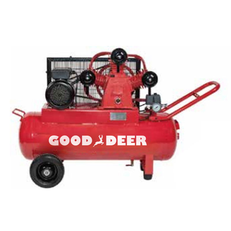
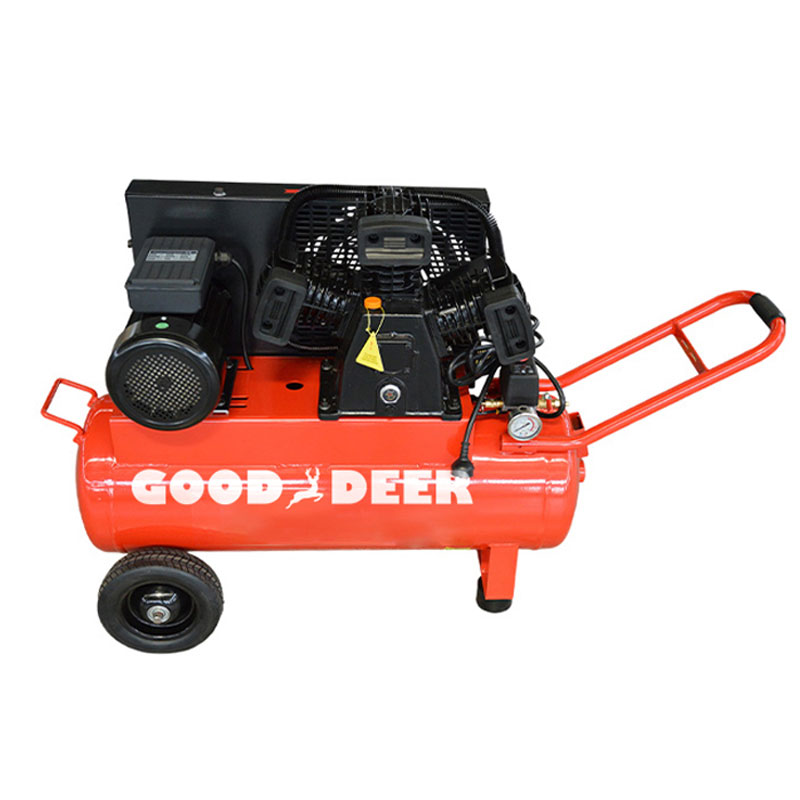
Piston Air Compressor Characteristics
A piston (reciprocating) air compressor uses one or more pistons driven by a crankshaft to compress air in cylinders. It operates on a duty cycle — typically 60–75% for single-stage and 50–60% for two-stage models — meaning it runs for a portion of each hour and rests for the remainder to prevent overheating. Key installation implications:
- Generates significant vibration due to reciprocating motion — requires rubber anti-vibration mounts and careful pipe connection design
- Produces higher noise levels: typically 75–90 dB(A) at 1 meter for industrial models
- Requires an integrated or separate air receiver tank to store compressed air and smooth pressure fluctuations
- Produces significant condensate in the receiver due to temperature cycling — automatic drain valves are essential
- Lower purchase cost; better suited to intermittent demand applications
Screw Air Compressor Characteristics
A rotary screw air compressor uses two intermeshing helical rotors to continuously compress air. It is designed for 100% continuous duty and is the preferred choice for industrial facilities with sustained compressed air demand exceeding 4–6 hours per day. Key installation implications:
- Generates substantial heat during operation — a 75 kW screw compressor dissipates approximately 68–70 kW as heat into the surrounding air, requiring dedicated ventilation or heat recovery systems
- Lower vibration than piston compressors — standard anti-vibration mounts are still recommended but flexible pipe connectors are less critical
- Lower noise levels in modern sound-attenuated enclosures: typically 62–75 dB(A) at 1 meter
- Requires oil-water separator for condensate disposal — screw compressor condensate contains compressor oil and cannot be discharged directly to drain in most jurisdictions
- Higher purchase cost; lower energy cost per unit of compressed air at sustained high utilization
| Parameter | Piston Compressor | Screw Compressor |
|---|---|---|
| Duty Cycle | 50–75% | 100% |
| Typical Noise Level | 75–90 dB(A) | 62–75 dB(A) |
| Vibration Level | High | Low–Medium |
| Heat Rejection | Moderate (intermittent) | High (continuous) |
| Receiver Tank Required | Yes (integrated or separate) | Recommended (separate) |
| Best Application | Intermittent demand, workshops | Continuous industrial production |
| Condensate Treatment | Drain from receiver | Oil-water separator required |
Step 1 — Site Selection and Preparation
The installation location is the single most consequential decision in compressor installation. An inadequate site causes overheating, excessive noise propagation, accelerated wear, and maintenance access problems that persist for the machine's entire service life.
Floor and Structural Requirements
Air compressors must be installed on a flat, level concrete floor capable of supporting the machine's operating weight. A 75 kW screw compressor with integrated dryer typically weighs 1,200–1,800 kg; ensure the floor load rating (typically specified in kN/m²) is verified by a structural engineer if there is any doubt. The floor must be level to within ±2 mm per meter — an unlevel compressor causes uneven oil distribution in screw units and accelerated bearing wear in piston units. For piston compressors above 15 kW, a dedicated inertia base (concrete pad) of 150–200 mm thickness extending at least 300 mm beyond the machine footprint on all sides is recommended to absorb vibration.
Clearance Distances for Service Access and Ventilation
Most compressor manufacturers specify minimum clearance distances in their installation manuals. As a general industry guideline:
- Front and sides (service access panels): Minimum 1,000 mm (1 meter) — sufficient for filter changes, oil changes, and belt inspections without repositioning the machine
- Rear (cooling air discharge for screw compressors): Minimum 1,500 mm — or ducted directly to the exterior to prevent recirculation of hot discharge air
- Above the unit: Minimum 1,000 mm for overhead maintenance and lifting access
- Between multiple compressors: Minimum 1,500–2,000 mm to prevent thermal interaction between units
Ambient Temperature and Ventilation Requirements
Most air compressors are rated for ambient temperatures of 5°C to 40°C (41°F to 104°F). Operating above 40°C ambient causes thermal shutdowns, accelerated oil degradation in screw compressors, and reduced motor lifespan. Ventilation airflow must be calculated based on the heat rejection of the unit. For a 37 kW screw compressor rejecting approximately 34 kW of heat, the required ventilation airflow at a 10°C temperature rise is:
Q (m³/s) = Heat rejection (kW) ÷ (1.2 × Cp × ΔT) = 34 ÷ (1.2 × 1.005 × 10) ≈ 2.8 m³/s (≈ 10,080 m³/hour)
This airflow must be delivered by either natural ventilation through large louvered openings or mechanical ventilation fans with ducting. Never install a compressor in a sealed or poorly ventilated room without calculating and providing adequate ventilation — this is the most frequently violated installation requirement and the leading cause of thermal shutdowns and premature compressor failure.
Intake Air Quality
Locate the compressor where intake air is clean, cool, and dry. Avoid locations near:
- Painting booths or solvent storage — solvent vapors in intake air are a fire hazard and contaminate compressed air
- Welding areas — metal dust and fumes accelerate valve and cylinder wear in piston compressors
- Steam or exhaust discharge points — elevated humidity dramatically increases condensate volume and corrosion rates
- Loading docks or outdoor areas without filtration — dust loading shortens intake filter life and enters the compression chamber
Step 2 — Electrical Connection: Sizing and Safety
Electrical installation for air compressors must be performed by a licensed electrician in compliance with local electrical codes (NEC in the USA, IEC 60364 in Europe, AS/NZS 3000 in Australia). Incorrect electrical installation is a fire hazard and immediately voids compressor warranties.
Determining Electrical Requirements
The three critical electrical parameters to establish before ordering cable and protection devices are:
- Full load current (FLC): Found on the motor nameplate. A 15 kW (20 HP) compressor motor at 400V three-phase draws approximately 28–30 A FLC.
- Starting current (inrush): Direct-on-line (DOL) starting draws 6–8× FLC at startup. A 15 kW DOL motor draws up to 210 A for 3–8 seconds during starting. Star-delta starters reduce this to approximately 2–3× FLC; variable frequency drives (VFDs) limit starting current to 1.0–1.5× FLC.
- Supply voltage and phase: Compressors above 2.2 kW (3 HP) are virtually always three-phase. Confirm the available supply voltage matches the motor nameplate — operating a 380V motor on a 415V supply continuously degrades insulation life.
Cable Sizing and Protection Device Selection
Cable cross-section must be sized for both the continuous current rating and the voltage drop over the cable run length. As a general guideline, voltage drop from the distribution panel to the compressor should not exceed 3% of supply voltage (12V on a 400V system). For runs exceeding 30 meters, upsize the cable by one conductor size above the minimum current rating requirement. Protection devices must be selected for motor starting characteristics:
- Circuit breaker: Use a motor-rated (Type D or motor protection) circuit breaker rated at 125–150% of FLC to tolerate starting inrush without nuisance tripping
- Motor overload relay: Set at 100–115% of FLC — provides thermal protection against sustained overload while allowing brief starting peaks to pass
- Isolation switch or lockable disconnector: A mandatory safety requirement — must be installed within sight of the compressor and lockable in the OFF position to enable safe maintenance
Grounding and Bonding
The compressor frame, motor body, and all metallic compressed air piping connected to the unit must be bonded to the facility ground (earth) system. Use a dedicated equipment grounding conductor sized at minimum 50% of the phase conductor cross-section (per NEC Table 250.122). Poor grounding is a shock hazard and contributes to static discharge events — particularly dangerous near painting and coating operations.
Step 3 — Vibration Isolation and Anti-Vibration Mounting
Vibration transmitted from a piston compressor to the building structure causes noise amplification, fatigue cracking in rigid pipe connections, loosening of fasteners, and premature wear of the compressor itself. Proper vibration isolation is not optional.
Anti-Vibration Mounts for Piston Compressors
Install anti-vibration rubber mounts (also called vibration isolators or pad mounts) under each foot of the compressor. Select mounts rated for the compressor operating weight divided by the number of mounting points, with a natural frequency of 3–8 Hz — well below the compressor operating frequency of typically 24–30 Hz (for 1,450–1,800 rpm machines). Over-stiff mounts (too high a natural frequency) provide no isolation benefit. For a 250 kg two-stage piston compressor on four mounting points, each mount carries approximately 62.5 kg — select mounts rated for 60–70 kg with appropriate deflection characteristics.
Flexible Pipe Connectors
Never connect rigid steel or copper pipe directly to the outlet of a piston compressor. The vibration transmitted through a rigid connection fatigues the pipe at the first fixed support point, causing cracks and leaks within months. Install a flexible hose connector or flexible metal braid connector at the compressor outlet — minimum 300–500 mm long for piston compressors, with a 90° change of direction preferred to maximize vibration absorption. The flexible connector must be rated for the maximum operating pressure and temperature of the system.
Step 4 — Compressed Air Piping System Installation
The compressed air distribution system connected to the compressor is as important as the compressor itself. A poorly designed piping system causes excessive pressure drop (reducing effective working pressure at tools), condensate accumulation (causing corrosion and contaminating pneumatic equipment), and leaks that force the compressor to run longer and harder than necessary.
Pipe Material Selection
- Aluminum pipe systems (e.g., Transair, Prevost): The modern preferred choice for most industrial installations. Lightweight, corrosion-free, leak-free push-fit or threaded connections, and fully reconfigurable. Suitable for pressures up to 13–16 bar depending on system. Higher initial cost than steel but lower installation labor cost and zero long-term corrosion maintenance.
- Galvanized steel pipe: Traditional choice, high pressure rating (up to 50 bar), widely available. Susceptible to internal corrosion and scale formation over time — rust particles contaminate air tools and instrumentation. Threaded joints require thread sealant (PTFE tape or pipe dope) and periodic re-tightening.
- Copper pipe: Excellent corrosion resistance, smooth internal bore minimizes pressure drop. Requires brazing or press-fit fittings — higher skill requirement for installation. Avoid direct contact between copper and aluminum (galvanic corrosion) without dielectric fittings.
- PVC or standard plastic pipe: NOT suitable for compressed air. PVC shatters under pressure impact and degrades with compressor oil — it is prohibited by OSHA and most industrial safety standards for compressed air service. Use only pipe specifically rated and labeled for compressed air service.
Pipe Sizing to Minimize Pressure Drop
The main header pipe from the compressor/receiver to the distribution ring should be sized to limit pressure drop to no more than 0.1 bar (1.5 psi) across the entire distribution system at maximum flow. As a practical sizing guide based on flow rate and pipe length:
| Compressor Output | Pipe Run up to 15m | Pipe Run 15–30m | Pipe Run 30–60m | Pipe Run 60–100m |
|---|---|---|---|---|
| Up to 200 L/min (7 CFM) | DN15 (½") | DN20 (¾") | DN25 (1") | DN32 (1¼") |
| 200–600 L/min (7–21 CFM) | DN20 (¾") | DN25 (1") | DN32 (1¼") | DN40 (1½") |
| 600–1,500 L/min (21–53 CFM) | DN25 (1") | DN32 (1¼") | DN40 (1½") | DN50 (2") |
| 1,500–4,000 L/min (53–141 CFM) | DN40 (1½") | DN50 (2") | DN65 (2½") | DN80 (3") |
Piping Layout and Condensate Management
Install all compressed air distribution piping with a minimum slope of 1:100 (10 mm per meter) in the direction of airflow, directing condensate toward low points where automatic drain valves are installed. Take all branch connections from the top of the main header — never from the bottom — to prevent condensate from running down into tools and equipment. Install a moisture separator and filter-regulator-lubricator (FRL) unit at each major point of use.
Step 5 — Safety Devices and Pressure System Compliance
Compressed air systems are classified as pressure vessels and pressure systems in most jurisdictions, subject to mandatory safety requirements. Non-compliance results in fines, insurance voidance, and — in the event of an incident — criminal liability.
Pressure Relief Valve
Every compressor and receiver tank must have a pressure relief valve (PRV) set at no more than 110% of the maximum allowable working pressure (MAWP) of the system. The PRV must be installed in the pressure line without any isolation valve between the PRV and the pressure source — it must always be able to operate. PRVs must be tested annually and replaced if they fail to reseat cleanly after testing.
Pressure Gauges and Automatic Controls
- Install a pressure gauge on the receiver outlet, visible from the compressor control panel. Gauge range should be 1.5–2× the operating pressure for accurate reading in the normal operating range.
- Set the compressor pressure switch or electronic controller to cut-in at 0.5 bar below and cut-out at the maximum rated working pressure. Pressure differential that is too narrow causes short-cycling, which damages motors and compressor components.
- Install a high-temperature shutdown sensor on screw compressors — most modern units have this integrated, but verify it is connected and calibrated to shut down at the manufacturer-specified limit (typically 105–115°C oil temperature).
Receiver Tank Inspection and Registration
Air receiver tanks are pressure vessels subject to periodic inspection requirements. In the EU, this falls under the Pressure Equipment Directive (PED 2014/68/EU); in the USA under ASME Section VIII and local jurisdiction requirements; in Australia under AS 3788. A new receiver tank must have a written scheme of examination established before first use, and inspection intervals are typically every 2 years for external inspection and every 4 years for internal inspection in most jurisdictions. Maintain an inspection logbook at or near the compressor.
Step 6 — Pre-Start Checks and First Commissioning Startup
The commissioning startup is when installation errors reveal themselves — often destructively if not caught beforehand. A systematic pre-start checklist prevents damage to a new machine.
Pre-Start Checklist for Piston Air Compressors
- Verify oil level in crankcase is at the correct level on the sight glass — never start a piston compressor without oil. Use the oil grade specified in the manual (typically SAE 30 or SAE 40 non-detergent compressor oil).
- Check that all bolts and fasteners are tight — vibration during transport loosens fasteners on new machines.
- Confirm the belt tension is correct (if belt-driven): deflection of 10–15 mm per 300 mm of belt span under moderate finger pressure is typical.
- Verify the unloader valve is functioning — this allows the compressor to start under no-load pressure, reducing starting torque.
- Open the receiver drain valve fully — start the compressor with the drain open to purge any residual moisture from the tank before closing the drain once pressure builds.
- Bump-start the motor (apply power momentarily) and observe rotation direction against the arrow on the flywheel or cooling fan — incorrect rotation direction destroys the compressor immediately. If incorrect, swap any two of the three phase supply wires.
- Run at no load for 5–10 minutes, monitoring for abnormal noise, vibration, or overheating before allowing pressure to build.
Pre-Start Checklist for Screw Air Compressors
- Check compressor oil level in the oil separator tank sight glass — fill with manufacturer-specified synthetic compressor oil if below the minimum mark. A typical 37 kW screw compressor requires approximately 12–16 liters of oil.
- Verify that the cooling air inlet and outlet paths are unobstructed — even temporary obstruction during startup can cause thermal shutdown.
- Confirm all electrical connections are tight and the control panel displays no fault codes.
- Check that the minimum pressure valve (typically set at 4–4.5 bar) is installed and functional — this maintains minimum oil circulation pressure during startup and load changes.
- Verify motor rotation direction using the bump-start method before allowing the compressor to start fully loaded.
- Start the compressor in unloaded mode and allow it to run for 3–5 minutes to circulate oil and warm up before loading.
- Monitor oil temperature, discharge temperature, and system pressure during the first loaded run — all should stabilize within manufacturer specifications within 10–15 minutes.
Post-Installation: Air Treatment Equipment You Should Add
A properly installed compressor delivers pressurized air — but not necessarily clean, dry, oil-free air suitable for sensitive applications. The following air treatment equipment should be considered part of the complete installation, not optional accessories.
- Refrigerant air dryer: Cools compressed air to a pressure dew point of typically +3°C, condensing and removing the majority of water vapor. Essential for any application where moisture would damage pneumatic tools, instruments, or cause corrosion in the distribution system. Install immediately downstream of the aftercooler and receiver.
- Particulate filter (coalescing filter): Removes compressor oil aerosols and particles down to 0.01 micron — required for painting, food processing, pharmaceutical, and electronics applications. Install downstream of the dryer.
- Activated carbon filter: Removes oil vapor and odor — required when compressed air contacts food, beverages, or breathing air applications. Install as the final stage after the coalescing filter.
- Automatic drain valves: Install on the receiver, aftercooler, dryer, and every filter bowl. Timer-operated or zero-loss demand drains prevent condensate accumulation without wasting compressed air through manual draining. A receiver without automatic draining accumulates liquid water that accelerates internal corrosion and contaminates downstream air.
- Oil-water separator: Mandatory for screw compressor condensate disposal. Separates compressor oil from condensate to achieve an oil content of less than 20 ppm — the threshold required for legal discharge to drain in most jurisdictions. Condensate discharge without an oil-water separator is an environmental violation in most countries.
Common Installation Mistakes and How to Avoid Them
The following errors are the most frequently observed across both piston and screw compressor installations, and each has a straightforward prevention:
- Undersizing the electrical supply: Using existing circuits not dedicated to the compressor causes nuisance tripping, voltage sag that harms the motor, and fire risk from overloaded conductors. Always install a dedicated circuit sized for 125% of FLC minimum.
- Installing in a confined or unventilated space: The compressor room heats up, pushing ambient temperature above 40°C, causing thermal shutdowns within hours of first operation. Always calculate and provide adequate ventilation airflow before installation.
- Connecting rigid pipe directly to the compressor outlet: On piston compressors especially, the first pipe joint cracks within weeks. Always install a flexible connector at the compressor outlet as the first piping component.
- Failing to check rotation direction before full start: Starting a compressor in reverse rotation — even briefly — destroys the oil pump in screw compressors and bends connecting rods in piston compressors. Always bump-start and verify rotation direction first.
- Using undersized distribution pipe: Pressure drop across undersized pipe forces the compressor to run at a higher cut-out pressure to compensate, increasing energy consumption and wear. Size the main header for <0.1 bar drop at maximum flow.
- Omitting automatic drain valves: Manual drains are routinely neglected in daily operations. Water accumulation in the receiver accelerates corrosion, causes water hammer, and contaminates pneumatic tools — automatic drains are a low-cost prevention for a high-cost problem.


